
This is far from being complete!
I was oscillating between this and something like Arduino/RaspberryPI. The reason I ended up with the MSP430 is simply because I wanted to be closer to the metal - and I felt like the other two just had… too much power (!!). I’m also 5 years late to the party but heh.
I should add - one of the cool things about the MSP430 Launchpad is that you essentially have a programming board (allowing you to debug on the fly etc…) but more importantly, you can then buy other microcontrollers and embed them in whatever you feel like.
Disclaimer: I have (had?) zero experience programming microcontrollers or any kind of hardware - let alone an understanding of electronics. Don’t hesitate to fact-check.
Programming the MSP430
There are a couple of IDEs available for the MSP430. Code Composer Studio by TI itself, and Energia (open-source, orginally for Arduino). I originally started with Energia. It’s dead easy to set up but does a really good job at abstracting certain things from you. And given my objective was to be closer to the metal (but not so close as to use assembly), I went back to CCS.
Note that in order to download CCS you’ll need to sign up for a TI account - and agree to some declaration saying you won’t use this technology to control nuclear plants and the like…
A (brief) note on interacting with the chip & hardware
The MSP430 provides a number of registers used to control various functions. Those registers can be used to interact with the hardware directly (that is, you can read the status of a pin, or set options on the pin itself by setting some bits in a register).
I think the technical term for this is memory-mapped I/O.
To illustrate this, let’s take a quick look a the watchdog timer.
WDTCTL
The watchdog timer is bit like a something monitoring your program and periodically asking “Is the program still running?”. If the program doesn’t answer, it forces the board to restart. You can deal with this in a number of ways (like telling it you’re fine ahead of time) - but for ease it’s often turned off.
WDTCTL is the watchdog control register. It allows us to interact with timer. In otherwords, setting various bits will cause the timer to behave in certain ways.
Now this is probably all rather confusing so let’s start writing some code and explain things along the way.
References:
Getting started (with CCS 6)
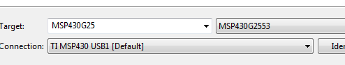
When creating a new project, you’ll need to specify the chip you are targetting. To figure that out, just look at the marking on the microcontroller itself. The larger of the two in my pack is M430G2553, and M430G2454 is the smaller one.
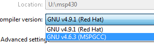
If you installed Energia, CCS will, by default, use the compiler that came with Energia - this can lead to some funky behaviour. You can install the one for CCS via Help -> CCS App Center and searching for GCC
Pick the right compiler:
And under Project templates and examples, pick the one with main.c. The file should look like the below:
#include <msp430.h>

/*
 * main.c
 */
int main(void) {
    WDTCTL = WDTPW | WDTHOLD; // Stop watchdog timer

  return 0;
}
Right away we see there are a number of variables being defined and state being set.
WDTCTL is the register used to interact with the watchdog timer. It’s a 16-bit register divided into two halves of 8 bits each. Setting the 7th bit (which is what WDTHOLD refers to) disables the timer.
The other variable, WDTPW, is the watchdog timer password. If we try to set a bit without this at the same time, the watchdog timer will think this is an error and cause a reset. I’m guessing this is there so we don’t assign random bits to this memory address by mistake (again - guessing).
Right - let’s get this compiled. In CCS you’ll notice a little bug and a hammer. If you used Eclipse before this will look very familiar.
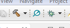
The hammer just builds the project (it doesn’t send it to the board). Click on the little bug and you’ll automatically be dropped in the debug view (called CCS Debug, in the top right corner - click on CCS Edit to go back to the previous view).
It will also break on the first line. Press F8 to continue the execution.
As expected, the program finishes - and does absolutely nothing. So let’s continue with the obligatory LED example.
Turning the lights on
Looking at the board, we see that LED1 is controlled by port P1.0. Each port has a dedicated 8-bit register, where each bit is associated with a pin. So bit 0 will control P1.0.
For instance, to turn the LED1 on we need to set the direction of the pin 0 on port 1 for output (by setting P1DIR’s leftmost bit to 11 - or ‘on’) - and the output to high (by setting P1OUT’s leftmost bit to 1).
int main(void) {
    WDTCTL = WDTPW | WDTHOLD; // Stop watchdog timer

    P1DIR  =  0x01;
    P1OUT  =  0x01;

  return 0;
}
Click Debug, and this will turn the LED1 on!
Just to illustrate the whole port vs pin concept, let’s turn the 2nd LED (LED2 - via P1.6) on.
P1 76543210
   01000001 // 0x41
In code:
P1DIR = 0x41;
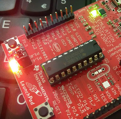
P1OUT = 0x41;And there - we have just turned on both LED1 and LED2 (red and green respectively, which you can not see from the picture below).
References:
Don’t push that button
Let’s see if we can get the push button working. For reasons well explained below (c.f. references below), we need to toggle the pull-up resistor for the P1.3 pin. The code looks like this:
int main(void) {
    WDTCTL = WDTPW | WDTHOLD; // Stop watchdog timer

    P1DIR |= 0x41;
    P1OUT |= 0x41;
    // we need to set the pull-up resistor as well as the output
    P1OUT |= BIT3;
    P1REN |= BIT3;

    for (;;) {
      if ((P1IN & BIT3) == 0) {
        P1OUT ^= 0x41;
      }
    }

  return 0;
}
It might sound a little counter-intuitive to set P1OUT |= BIT3 but that’s how it works (TODO: figure out why it’s counter-intuitive!).
When the button is pressed down, the 3rd bit P1IN gets set to 0 - and we then toggle the state of the LEDs.
However this is woefully inefficient. We’re essentially polling for state at every iteration. And if there’s any jitter it’ll lead to funky behaviour (this is because this loop gets executed constantly - we can see it more clearly if we add a delay after the if - something like for (int i=0;i<6000;i++) {}).
So let’s move to interrupts next.
References:
Interrupts
The CPU can be interrupted if a particular situation occurs - for instance, if the watchdog timer hits the max.